Tinyfox Upgrade
It is possible to upgrade built-up Tinyfox transmitters with older versions of the PCB to the newest software version.
Upgrading is done by just replacing the microcontroller by an ATtiny25 or ATtiny45 (containing the actual software version).
However, for measuring the battery voltage a hardware modification is required:
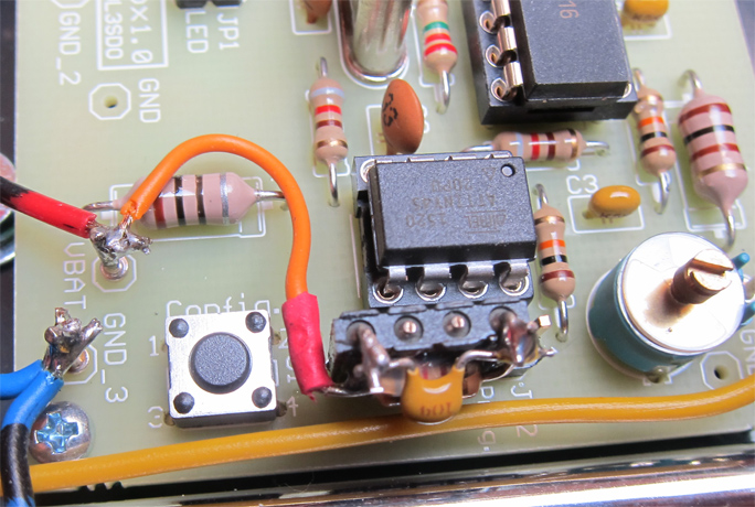
Pin 7 (PB2) of the µC is connected to the battery voltage through a resistor (820Ohm).
Pin 7 (PB2) is connected to ground through a capacitor (100nF).
This circuitry is part of the PCB version 4.0 and higher, see schematic.
Since PB2 is required in case the µC shall be reprogrammed in circuit and thus is present at JP2,
it may be beneficial to make the connection to JP2 pluggable.
PCB version 1.0 |
Variant with 4-pin tilted precision female connector (Conrad part no. 738675).
Cut off the two unused pins and solder the components accordingly.
Modification by DF7SF with flexible wire connection.

|
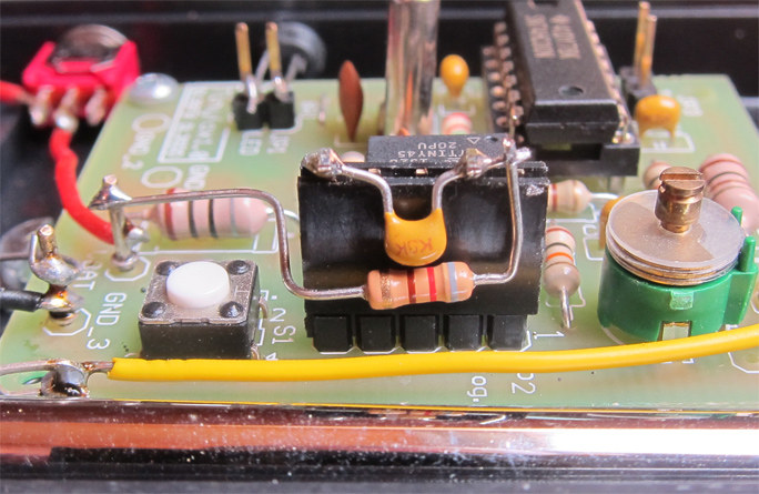
Variant with 5-pin tilted female connector (Conrad part no. 1303432).
Cut off the three unused pins and solder the components accordingly.

|
PCB version 2.0 |
Various female connectors can be used, either with 4 pins or 6 pins.
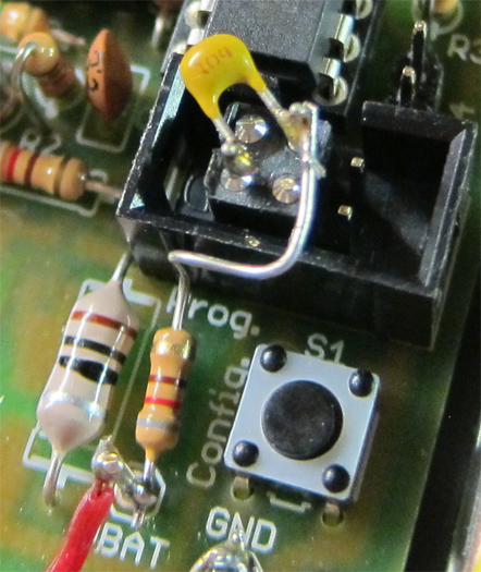
Cut off the unused pins and solder the components accordingly.
Example with 4-pin precision female connector (Conrad part no. 1311389):

|


